Digital Logic Gates
CSC 105 - The Digital Age - Weinman
- Summary:
- We discuss the basics of electronic digital logic, the
foundation of computing hardware.
Background
Up to this point we have been thinking about the logical building
blocks of computation: bits. You've learned how to represent integers,
fractions, and images using zeros and ones, as well as how to add
bits that represent positive and negative numbers. So why do we bother
with these digital bits and not the customary decimal digits? The
main reason is that building computers to use bits is much easier.
While early computers were mechanical, representing their computations
and information (switch states) via the physical configuration of
gears and the like, today's computation uses electricity to represent
state and electrical properties to control the flow of algorithms.
How? Let's start from the bottom and work our way up.
In common terminology, a circuit is a closed path or loop where
the end point is the same as the start point. Electricity flows along
or around a set of wires much like walkers along a circuit path. Transistors
are essentially electrical switches that route electricity through
a set of wires, in the same way that railroad switches route the flow
of trains along tracks. An electrical voltage applied to one pair
of wires can change the voltage on another pair of wires. It turns
out these transistors are the most basic elements of electronic circuits.
However, assembling transistors into useful circuits was extraordinarily
sensitive, complicated, and expensive. Robert Noyce, whom our building
is named for, is credited with inventing the so-called "integrated
circuit," which allowed his company to mass-produce pre-packaged
transistors into more complicated circuits. This development help
give rise to the electronic "digital age."
In digital computers, a wire at any point along a circuit carries
"high" voltage (typically around five volts, 5V) or a "low"
voltage (around zero volts, 0V). These two states of the wire are
considered mutually exclusive and can be thought of as "on"
(5V) and "off" (0V) or more abstractly "true" and "false."
We might even think of them as our familiar digital bits 0
and 1.
These two states form the foundation of Boolean logic, a useful
system of reasoning about things that have just two states, typically
referred to as true and false. This logic is named for George Boole
(1815-1864), the British mathematician and logician who described
it. As you might guess, this logic forms the foundation of digital
circuitry. In the discussion that follows, we will be talking about
electricity on wires and this binary (two-stated) logic interchangeably.
Logic Gates
Imagine an input wire, which we'll call x, that can take on two
states. For shorthand, we call the false state 0 and the
true state 1. What can we do with these values? If they represent
our familiar bits, we might want to figure out how to encode in
electricity the rules we've been using to add two bits together.
In this reading and the subsequent class period, we'll put together
the building blocks for this process.
Boolean Negation
What can we do with a single wire whose value is represented by x?
Not a whole lot, but we can do one thing: "negate" the value
of x. This process of logical negation means giving something its
opposite value. If something is NOT false, what must it be? We only
have two possible states, so if it's NOT false it must be true. Similarly,
if something is NOT true, it must therefore be false. (Pause here
before going on and make sure you understand perfectly those last
two sentences.)
If that "something" is x, we are talking about the value
of NOT x. We might represent this in the following table
where the left hand column shows the input, which we've labeled x,
and the right column shows its logical negation, which we've titled
NOT x.
Quite simply, the NOT operator "flips the bit."
How could we draw a diagram of an electronic circuit? The convention
is to indicate electrical wires (that carry a voltage) as lines. What
if we want to flip the voltage along the wire from high to low (true
to false, 0 to 1, etc.) or low to high? We need
a symbol that indicates this NOT operation. The symbol is called a
NOT "gate". For instance, in the diagram below, the current
flows from left to right along the wire, and the triangle next to
the circle indicates a NOT gate. The input wire to this gate is labeled
x, and the output wire is NOT x after it has gone through
the NOT gate.
| Circuit: | x |  | NOT x |
| Meaning: | input | NOT Gate | output |
Boolean AND
If we have two input values (wires) to think about, things
can get a lot more interesting. Let's call these two input values
x1 and x2. It might be useful to have a circuit indicates
when both of these values are true (high, 1, etc.).
Thus, we'd have two input wires to a gate, and one output wire. This
output wire would only be true when both of its inputs were true.
Using a table much like we had for the NOT gate, we can specify the
output of the gate for every possible input. As it turns out, the
name of this gate is the rather intuitive AND gate, because the output
is only true when x1 AND x2 are true. Thus, the only 1
in the table is in the bottom row, where both x1=1
and x2=1.
| x1 | x2 | x1 AND x2 |
|
| 0 | 0 | 0 |
| 0 | 1 | 0 |
| 1 | 0 | 0 |
| 1 | 1 | 1 |
As you might guess, this operator is also useful to represent in an
electronic circuit. The so-called AND gate is shown below.
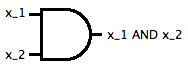 Like the NOT gate, it is read from left to right, with the two input
wires x1 and x2 on the left and the output wire, representing
the value x1 AND x2 on the right.
Like the NOT gate, it is read from left to right, with the two input
wires x1 and x2 on the left and the output wire, representing
the value x1 AND x2 on the right.
Boolean OR
In English, the word "or" can be somewhat ambiguous. Consider
the following two common phrases:
- cream or sugar
- coffee or tea
The first usage of the English "or" means "either one or
both," while the second usage means "which one, exclusively."
Of course, context helps us disambiguate these. That's not a useful
strategy for a circuit, so in Boolean logic, we specify that an OR
has the first meaning.
In addition to being able to combine two wires with an AND gate, we
might want to reason about whether either one of the two inputs x1
and x2 were 1 (true, high, etc.) Thus, the only case
for which the OR operator is false is when both inputs are false.
In the other three possible cases, at least one of the inputs is true,
meaning the output is true. We indicate this with a similar table
for the Boolean OR operator.
| x1 | x2 | x1 OR x2 |
|
| 0 | 0 | 0 |
| 0 | 1 | 1 |
| 1 | 0 | 1 |
| 1 | 1 | 1 |
The OR operator has a gate representation as well. The OR gate represented
below is read from left to right with the two input wires on the left
and the output wire on the right.

Digital Circuits
The three logic gates above give us the foundations for electronic
digital circuits, which are at the heart of today's computers. We
can combine and connect these gates to build bigger and more interesting
circuits. For instance, the circuit below is represented with three
input wires, x1, x2, and x3. We connect an AND gate,
using its output as the input to an OR gate.
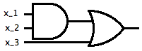 The result gives us a circuit whose output wire is the Boolean function
(x1 AND x2) OR x3.
Perhaps this circuit represents your function for determining whether
to come to class. Say x1 represents whether there is a homework
assignment due today, x2 represents whether you've completed
it, and x3 represents whether we are doing a lab exercise. Thus,
one condition for your coming to class would be homework is due AND
you've completed it. Another condition is we are doing a lab. If one
OR the other is true, you'd come to class.
Of course, I don't recommend using this circuit in your decision-making
process, because you'll miss out on the fact that in class we'll see
how to use these gates to build circuits that represent the other
form of the English "or", how to "remember" a value, and
how to add two bits together, including representing the carry.
The result gives us a circuit whose output wire is the Boolean function
(x1 AND x2) OR x3.
Perhaps this circuit represents your function for determining whether
to come to class. Say x1 represents whether there is a homework
assignment due today, x2 represents whether you've completed
it, and x3 represents whether we are doing a lab exercise. Thus,
one condition for your coming to class would be homework is due AND
you've completed it. Another condition is we are doing a lab. If one
OR the other is true, you'd come to class.
Of course, I don't recommend using this circuit in your decision-making
process, because you'll miss out on the fact that in class we'll see
how to use these gates to build circuits that represent the other
form of the English "or", how to "remember" a value, and
how to add two bits together, including representing the carry.
Acknowledgments
Adapted from materials by Marge Coahran. Used by permission.
Copyright © 2011 Jerod
Weinman.
 This work is licensed under
a Creative
Commons Attribution-Noncommercial-Share Alike 3.0 United States License.
This work is licensed under
a Creative
Commons Attribution-Noncommercial-Share Alike 3.0 United States License.