Kirchhoff's Law
Introduction
In addition to Ohm's Law, there is another fundamental law of electrical circuits we will need to understand: Kirchhoff's Voltage Law. Before we can fully appreciate and apply it, though we need to understand the notion of voltage drop.
Voltage Drop
Ohm's Law was our first introduction to the notion of a voltage drop, and our first application of it subtly tied to use Kirchhoff's Voltage Law as well.
Electrical components like resistors and diodes generally decrease the electric potential along a circuit, and that decrease is called the voltage drop. Ohm's Law describes the voltage drop across a resistor: linear in the amount of current.
Unlike resistors, which are passive components, LEDs and transistors are semiconductors. While semiconductors also drop the voltage on a circuit, no simple law says what this voltage drop will be. Fortunately, for a given semiconductor component, we will usually be able to assume it is a constant. No fancy math needed. Instead, we rely on the manufacturer's datasheet to tell us many characteristics of the device, including its safe operating ranges for current or voltage and (importantly) the voltage drops across terminals where current flows.
The voltage drop for a typical LED will be something on the order of 1–3V, usually depending on the color. We said earlier that the forward voltage is usually the voltage drop, and we will continue that assumption. Greater current flowing through an LED will result in a substantially greater voltage drop, but because we usually limit the current to being well within the tolerances of the LED, the actual voltage drop will be very near the forward voltage, considering how quickly the V-I curve rises.
So what does this mean for us? Let's revisit a prior analysis after taking a harder look at Kirchhoff's Law.
Kirchhoff's Law
Put simply, Kirchhoff's Voltage Law (KVL) is
The sum of the (signed) voltages around a loop is zero.
To explain, let's return to the simple battery, resistor, and LED circuit from the previous reading:
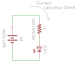
To keep the LED under its maximum current rating of 20mA, we proposed using Ohm's law to determine we need a resistor of 500Ω. However, that naïve analysis ignored two important facts: LED voltage drop and Kirchhoff's Law. Let's remedy that now.
Remember that Kirchhoff's Law tells us the sum of the voltages around a loop should be zero. For the simple battery, resistor, and LED circuit above, we have three terms to sum — the voltages of each:

The voltage across the battery terminals (from − to +) is given (9V), and the LED's datasheet might tell us that its forward voltage is 1.85V. Ohm's Law tells us that the voltage drop across the resistor depends on the current and its resistance. If we want to limit the current to 18mA as before, the only term remaining in the equation above is the resistance. Substituting these into Kirchhoff's Law above gives:

Note that we subtract the voltages across the resistor and LED, while adding the battery's voltage. That's because the resistor and the LED each involve a voltage drop.
Solving this equation for R shows us we need only around 400Ω for our resistor. This is lower than the 500Ω given by the original analysis because when we account for the voltage drop of the LED, the voltage drop across the resistor is lower, which means we can lower the resistance to get the same current.
Another Example
Let's correct another example from earlier in the reading, which introduced the notion of an ideal diode.
The approximating analysis below shows the current through the circuit on the left to be 5mA.
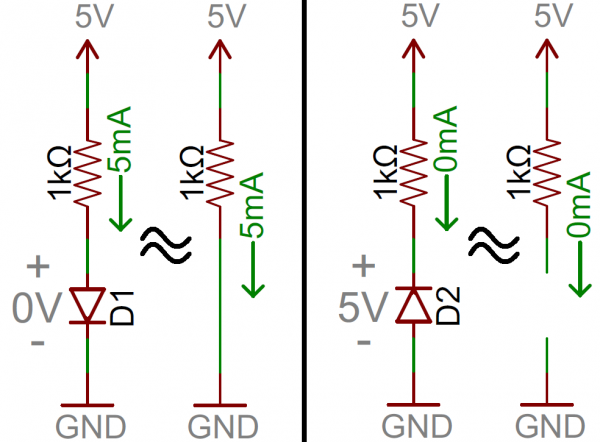
In the last example, the desired current was given and we calculated the necessary resistance. Here, the resistance is given and we should like to calculate the actual current. Instead of an ideal diode, suppose D1 has a forward voltage of 1V (to make the math somewhat easier).
Applying Kirchhoff's law, 1V across the diode D1 leaves 4V across the resistor, which we'll call R1. We finish by using Ohm's law to determine the current through the resistor: IR1 = VR1 / RR1 = 4V / 1KΩ = 4mA.
Finally, note that the analysis for the circuit at right is already correct. The voltage across the reverse-biased diode D2 is shown to be 5V. We'd conclude by Kirchhoff's law that the voltage across the resistor must be 0V (since the diode has already accounted for all the voltage from the power supply at the top of the circuit). Ohm's Law would then lead us to the conclusion that, if the voltage across the resistor is 0V, then the current through the resistor must be IR2 = VR2 / RR2 = 0V / 1KΩ = 0mA.
Conversely, in this particular scenario we might have reasoned better in the other direction first. When a diode is reverse biased, there is no (basically) current through it. No current through the diode means no current through the resistor. That observation allows us to apply Ohm's Law first to determine that VR2 = IR2 × RR2 = 0A × 1KΩ = 0V. Only after establishing the voltage across the resistor to be 0V would we then use Kirchoff's law to conclude the remaining voltage must be 5V across the diode.
Nifty! Kirchhoff and Ohm go hand in hand (plus the semiconductor datasheets) for a complete circuit analysis.