Resistors
Take a Stance, The Resist Stance
Resistors—the most ubiquitous of electronic components. They are a critical piece in just about every circuit. And their behavior in a circuit is described by one of our favorite equations, Ohm’s Law.

In this, our pièce de résistance, we’ll cover:
- What is a resistor?!
- Resistor units
- Resistor circuit symbol(s)
- Resistors in series and parallel
- Color coding decoding
- Example resistor applications
Resistor Basics
Resistors are electronic components which have a specific, never-changing electrical resistance. The resistor’s resistance limits the flow of electrons through a circuit.
They are passive components, meaning they only consume power (and can’t generate it). Resistors are usually added to circuits where they complement active components like op-amps, microcontrollers, and other integrated circuits. Commonly resistors are used to limit current, divide voltages, and pull-up I/O lines.
Resistor units
The electrical resistance of a resistor is measured in ohms. The symbol for an ohm is the greek capital-omega: Ω. The (somewhat roundabout) definition of 1Ω is the resistance between two points where 1 volt (1V) of applied potential energy will push 1 ampere (1A) of current.
As SI units go, larger or smaller values of ohms can be matched with a prefix like kilo-, mega-, or giga-, to make large values easier to read. It’s very common to see resistors in the kilohm (kΩ) and megaohm (MΩ) range (much less common to see milliohm (mΩ) resistors). For example, a 4,700Ω resistor is equivalent to a 4.7kΩ resistor, and a 5,600,000Ω resistor can be written as 5,600kΩ or (more commonly as) 5.6MΩ.
Schematic symbol
All resistors have two terminals, one connection on each end of the resistor. When drawn on a schematic diagram, a resistor will show up as one of these two symbols:
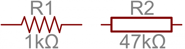
Two common resistor schematic symbols. R1 is an American-style 1kΩ resistor, and R2 is an international-style 47kΩ resistor.
The terminals of the resistor are each of the lines extending from the squiggle (or rectangle). Those are what connect to the rest of the circuit.
The resistor circuit symbols are usually enhanced with both a resistance value and a name. The value, displayed in ohms, is obviously critical for both evaluating and actually constructing the circuit. The name of the resistor is usually an R preceding a number. Each resistor in a circuit should have a unique name/number. For example, here’s a few resistors in action on a 555 timer circuit:
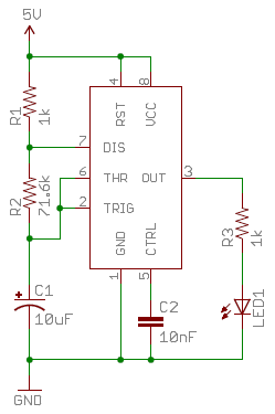
In this circuit, resistors play a key role in setting the frequency of the 555 timer’s output. Another resistor (R3) limits the current through an LED.
Decoding the color bands
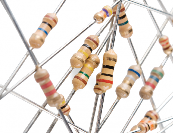
Through-hole, axial resistors (the kind used in our labs) usually use a color-band system to display their value. Most of these resistors will have four bands of color circling the resistor.
The first two bands indicate the two most-significant digits of the resistor’s value. The third band is a weight value, which multiplies the two significant digits by a power of ten.
The final band indicates the tolerance of the resistor. The tolerance explains how much more or less the actual resistance of the resistor can be compared to what its nominal value is. No resistor is made to perfection, and different manufacturing processes will result in better or worse tolerances. For example, a 1kΩ resistor with 5% tolerance could actually be anywhere between 0.95kΩ and 1.05kΩ.
How do you tell which band is first and last? The last, tolerance band is often clearly separated from the value bands, and usually it’ll either be silver or gold.
Here’s a table of each of the colors and which value, multiplier or tolerance they represent:
| Color | Digit value | Multiplier | Multiplied Out | Tolerance |
| Black | 0 | 100 | 1 | |
| Brown | 1 | 101 | 10 | |
| Red | 2 | 102 | 100 | |
| Orange | 3 | 103 | 1,000 | |
| Yellow | 4 | 104 | 10000 | |
| Green | 5 | 105 | 100,000 | |
| Blue | 6 | 106 | 1,000,000 | |
| Violet | 7 | 107 | 10,000,000 | |
| Gray | 8 | 108 | 100,000,000 | |
| White | 9 | 109 | 1,000,000,000 | |
| Gold | ±5% | |||
| Silver | ±10% |
Here’s an example of a 4.7kΩ resistor with four color bands:
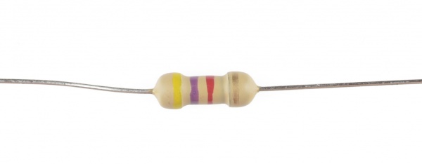
When decoding the resistor color bands, consult a resistor color code table like the one above. For the first two bands, find that color’s corresponding digit value. The 4.7kΩ resistor has color bands of yellow and violet to begin - which have digit values of 4 and 7 (47). The third band of the 4.7kΩ is red, which indicates that the 47 should be multiplied by 102 (or 100). 47 times 100 is 4,700!
If you’re trying to commit the color band code to memory, a mnemonic device might help. There are a handful of (sometimes unsavory) mnemonics out there, to help remember the resistor color code. A good one, which spells out the difference between black and brown is:
Or, if you remember “ROY G. BIV”, subtract the indigo (poor indigo, no one remembers indigo), and add black and brown to the front and gray and white to the back of the classic rainbow color-order.
Color Code Calculator
If you’d rather skip the math (we won’t judge :), and just use a handy calculator, give this a try!
| Band 1 | Band 2 | Band 3 | Band 4 | |
| Value 1 (MSV) | Value 2 | Weight | Tolerance | |
Resistance: |
| |||
Series and Parallel Resistors
Resistors are paired together all the time in electronics, usually in either a series or parallel circuit. When resistors are combined in series or parallel, they create a total resistance, which can be calculated using one of two equations. Knowing how resistor values combine comes in handy if you need to create a specific resistor value.
Series resistors
When connected in series resistor values simply add up.


N resistors in series. The total resistance is the sum of all series resistors.
So, for example, if you just have to have a 12.33kΩ resistor, seek out some of the more common resistor values of 12kΩ and 330Ω, and butt them up together in series.
Parallel resistors
Finding the resistance of resistors in parallel isn’t quite so easy. The total resistance of N resistors in parallel is the inverse of the sum of all inverse resistances. This equation might make more sense than that last sentence:
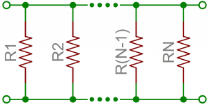
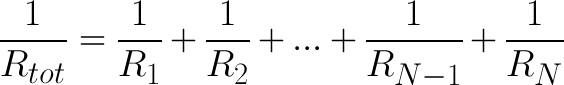
N resistors in parallel. To find the total resistance, invert each resistance value, add them up, and then invert that.
(The inverse of resistance is actually called conductance, so put more succinctly: the conductance of parallel resistors is the sum of each of their conductances).
As a special case of this equation: if you have just two resistors in parallel, their total resistance can be calculated with this slightly-less-inverted equation (a quantity known as the harmonic mean):
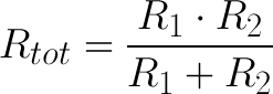
As an even more special case of that equation, if you have two parallel resistors of equal value the total resistance is half of their value. For example, if two 10kΩ resistors are in parallel, their total resistance is 5kΩ.
A shorthand way of saying two resistors are in parallel is by using the parallel operator: ||. For example, if R1 is in parallel with R2, the conceptual equation could be written as R1||R2. Much cleaner, and hides all those nasty fractions!
Example Applications
Resistors exist in just about every electronic circuit ever. Here are a few examples of circuits, which heavily depend on our resistor friends.
LED Current Limiting
Resistors are key in making sure LEDs don’t blow up when power is applied. By connecting a resistor in series with an LED, current flowing through the two components can be limited to a safe value.
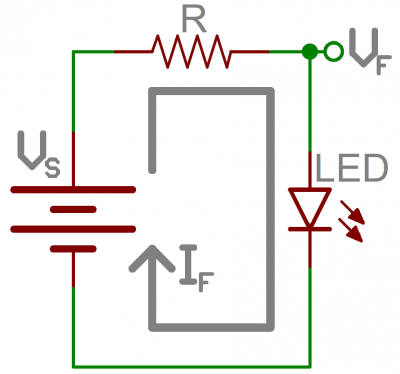
When sizing out a current-limiting resistor, look for two characteristic values of the LED: the typical forward voltage, and the maximum forward current. We'll discuss forward voltage more in the next reading on diodes, but all you need to know for now is that forward voltage is the voltage required to make an LED light up, and it varies (usually somewhere between 1.7V and 3.4V) depending upon the color of the LED. The maximum forward current is usually around 20mA for basic LEDs; continuous current through the LED should always be equal to or less than that current rating.
Once you’ve gotten ahold of those two values, you can size up a current-limiting resistor with this equation:
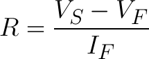
VS is the source voltage – usually a battery or power supply voltage. VF and IF are the LED’s forward voltage and the desired current that runs through it.
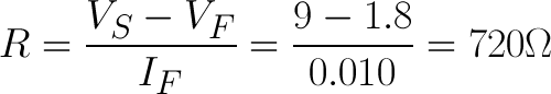
For example, assume you have a 9V battery to power an LED. If your LED is red, it might have a forward voltage around 1.8V. If you want to limit the current to 10mA, use a series resistor of about 720Ω.
Voltage Dividers
A voltage divider is a resistor circuit which turns a large voltage into a smaller one. Using just two resistors in series, an output voltage can be created that’s a fraction of the input voltage.
Here’s the voltage divider circuit:
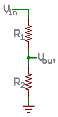
Two resistors, R1 and R2, are connected in series and a voltage source (Vin) is connected across them. The voltage from Vout to GND can be calculated as:
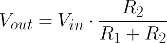
For example, if R1 was 1.7kΩ and R2 was 3.3kΩ, a 5V input voltage could be turned into 3.3V at the Vout terminal.
Voltage dividers are very handy for reading resistive sensors, like photocells, flex sensors, and force-sensitive resistors. One half of the voltage divider is the sensor, and the part is a static resistor. The output voltage between the two components is connected to an analog-to-digital converter on a microcontroller (MCU) to read the sensor’s value.
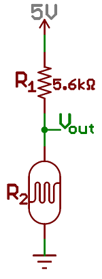
Here a resistor R1 and a photocell create a voltage divider to create a variable voltage output.
Once we finish learning about Kirchhoff's Voltage Law, you'll understand how to derive this equation for the voltage divider.
Pull-up Resistors
A pull-up resistor is used when you need to bias the input pin of another circuit component (e.g., a microcontroller, or MCU) to a known state. One end of the resistor is connected to input pin, and the other end is connected to a high voltage (usually 5V or 3.3V).
Without a pull-up resistor, inputs on the MCU could be left floating. There’s no guarantee that a floating pin is either high (5V) or low (0V).
Pull-up resistors are often used when interfacing with a button or switch input. The pull-up resistor can bias the input-pin when the switch is open, and it will protect the circuit from a short when the switch is closed.
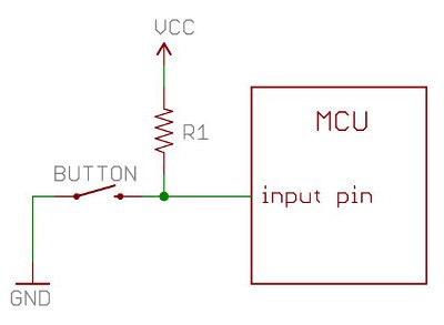
In the circuit above, when the switch is open the MCU’s input pin is connected through the resistor to 5V. When the switch closes, the input pin is connected directly to GND.
The value of a pull-up resistor doesn’t usually need to be anything specific. But it should be high enough that not too much power is lost if 5V or so is applied across it. Usually values around 10kΩ work well.
We will see more applications of pull resistors in the next class's reading when we learn about transistors and using them to build logic gates.
Conclusion
In this reading we introduced how to identify the resistance of a physical
resistor, measured in Ohms, using its color coded bands. We also explored the
notion of effective resistance
for multiple resistors in parallel or
series. Resistors have many applications, including limiting current,
adjusting voltage, and biasing inputs. We'll understand how to derive the
equations in this reading once we conclude the reading on Kirchoff's
Law(s).